
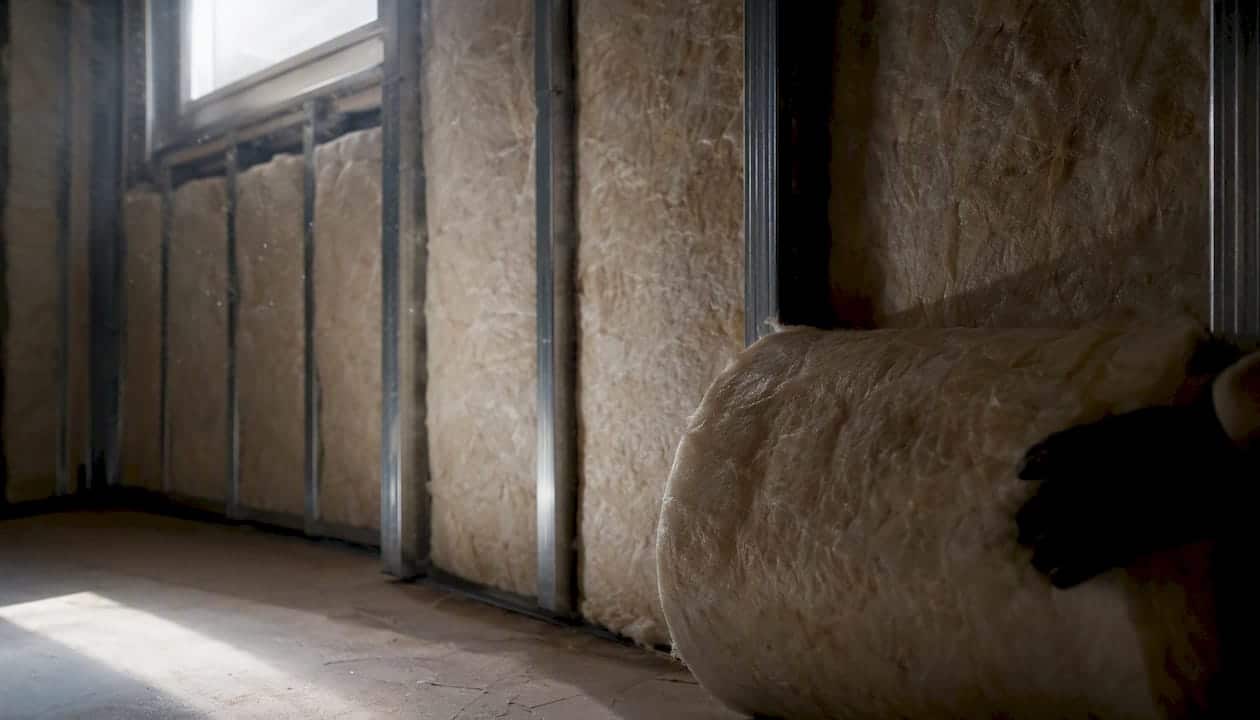
Fiberglass insulation works well in metal buildings, provided moisture is managed from the design stage onwards. Glass mineral wool remains one of the most widely specified insulants for built-up metal roofs and walls because it is non-combustible, lightweight, and inexpensive relative to its thermal performance. The catch is that fiberglass has almost no resistance to water vapour, so it fails when it sits against cold metal without a properly specified vapour control layer.
MCRMA guidance sets out installation best practice for mineral wool in built-up cladding systems. Approved Document L requires designers to calculate U-values that account for thermal bridging from rails and brackets, not just the insulation’s nominal performance. Glass mineral wool typically delivers a thermal conductivity of 0.035–0.045 W/mK, a respectable figure that puts it firmly in contention against rock wool and, for some applications, rigid boards.
For most new-build metal buildings, vinyl-faced fiberglass rolls are the sensible default. Consider alternatives when the project has unusual moisture loads, very tight cavity depths, or a need for higher performance per millimetre:
- Standard commercial or agricultural buildings with normal humidity: vinyl-faced fiberglass rolls, correctly detailed with an air and vapour control layer (AVCL).
- High-humidity interiors (food processing, swimming pools, wash-down areas): closed-cell spray foam or a reinforced vapour strategy alongside mineral wool.
- Thin assemblies or retrofit projects with limited depth: PIR or rigid insulation boards.
- Fire-sensitive applications or where combustible insulants are restricted: mineral wool or rock wool for its Euroclass A1 rating.
Key Takeaways
Fiberglass insulation performs reliably in metal buildings only when paired with a correctly positioned air and vapour control layer and a design-stage U-value calculation.
| Point | Details |
|---|---|
| Verdict on fiberglass | Suitable for most metal buildings, provided an AVCL and condensation strategy are specified alongside it. |
| Thermal performance range | Glass mineral wool typically delivers 0.035–0.045 W/mK; confirm the exact figure against the product data sheet. |
| AVCL vapour resistance target | Aim for 5,000–7,000 MN·s/g, positioned on the warm side of the insulation, per LABCW guidance. |
| Thermal bridging matters | Rails and brackets can significantly worsen effective U-value versus the insulation’s nominal figure; calculate, don’t assume. |
| Retrofit risk is higher | Always run a condensation risk analysis before retrofitting insulation into an existing metal building. |
| Alternatives exist for a reason | Choose spray foam for thin assemblies and air-sealing, PIR for high-performance retrofits, mineral wool for fire-rated builds. |
If a project needs a broader look at how insulation choices feed into overall building performance, Homeenergymodel’s Home Energy Model explained guide covers how fabric decisions like these connect to compliance and modelling requirements under the UK’s evolving energy standards.
Table of Contents
- How fiberglass insulation for metal buildings actually performs
- Fiberglass product options for metal buildings
- Why fiberglass fails in metal buildings and how to prevent it
- Installing fiberglass in purlin and girt systems step by step
- Do you need a vapour barrier, and how does ventilation help?
- Getting the thickness right: R-values, U-values, and Approved Document L
- When mineral wool, spray foam, or PIR beats fiberglass
- Budgeting for materials and labour on a metal building project
- Retrofitting fiberglass without creating a condensation problem
- What to check before you specify or hire
- What MCRMA, Approved Document L, and industry guidance actually require
- Homeenergymodel’s take on fitting insulation to the building’s real use
- Frequently asked questions
- Sources
How fiberglass insulation for metal buildings actually performs
Glass mineral wool works by trapping still air between fine glass fibres, and still air is a poor conductor of heat. That’s the entire mechanism: no chemistry, no phase change, just millions of tiny air pockets that slow heat transfer. The result is a thermal conductivity of roughly 0.035–0.045 W/mK, depending on density and fibre orientation, and a reaction-to-fire classification of Euroclass A1 under BS EN 13501-1, meaning it does not burn or contribute to fire spread. That combination of non-combustibility and low cost explains why it dominates built-up metal roofing and cladding specifications across the UK and beyond.
The strengths are genuine. Fiberglass is cheap relative to PIR or spray foam, light enough to handle without mechanical lifting on most roof pitches, and forgiving during transport because it recovers its thickness after compression once unwrapped. It also installs quickly in a built-up system, where rolls or batts sit between purlins or girts and are covered by an inner liner. None of that is in dispute.
The limitations are where projects go wrong. Fiberglass has negligible vapour resistance on its own, so if warm, moist internal air reaches the cold underside of an external metal sheet through or around the insulation, it condenses. Water in the wool reduces its insulating value and can encourage corrosion of the steel it’s meant to protect. Mineral wool is also vulnerable to compression from careless handling, sagging over time if not properly supported, and thermal bridging where spacer rails and brackets punch through the insulation layer and create a direct path for heat loss.
- Open-cell structure traps air but offers almost no resistance to vapour movement.
- Euroclass A1 rating suits fire-sensitive builds without extra protective boarding.
- Recovery after compression restores loft, but only if handling follows manufacturer guidance.
- Thermal bridging from rails can meaningfully worsen the calculated U-value versus the insulation’s centre-of-cavity figure.
Pro Tip: Never judge a fiberglass system by the nominal R-value printed on the roll. Ask for the whole-assembly U-value calculation that accounts for rail bridging, because that’s the number Building Control actually cares about.
Fiberglass product options for metal buildings
Specification comes down to three real choices: vinyl-faced rolls, batts, and quilts, each with facing variants that change how they behave once installed.
Vinyl-faced insulation rolls are the standard product for purlin and girt assemblies in metal buildings. The vinyl facing is stitched or laminated onto one side of the glass mineral wool and, according to industry installation guidance, the facing often functions as an integral vapour retarder for many commercial applications. That matters because it removes the need for a separate polythene vapour barrier in a large share of standard-humidity buildings, though very humid interiors or extreme heating regimes still warrant a dedicated barrier layer.
Faced, unfaced, and foil-backed products each suit different roles. Faced batts (vinyl or kraft paper) go on show in occupied spaces where the facing doubles as an interior finish and vapour control measure. Unfaced batts suit applications where a separate liner or membrane will handle both vapour control and appearance, such as when a composite liner panel is specified over the insulation. Foil-backed variants add a reflective layer that can contribute a modest radiant benefit in ventilated cavities, though this is a secondary consideration next to the base R-value.
Density and roll width affect real-world performance more than most specifications acknowledge. Rolls commonly come in widths around 1,200 mm to match standard purlin and girt spacing, and they arrive compression-wrapped for transport. MCRMA guidance is explicit that installers must allow the product to recover its full thickness before sheeting over it. A roll that’s still compressed when the outer sheet goes on will never deliver its declared R-value, no matter how good the product data sheet looks.
- Vinyl-faced rolls: the default choice for new-build purlin/girt systems.
- Faced batts: best where the facing is also the visible interior finish.
- Unfaced batts: suited to assemblies with a separate liner or vapour membrane.
- Foil-backed rolls: a minor radiant boost in ventilated void applications.
Why fiberglass fails in metal buildings and how to prevent it
Condensation is the single biggest cause of insulation failure in metal buildings, and it’s entirely predictable once you understand the mechanism. Warm, moisture-laden air inside the building migrates towards the cold outer skin. If it reaches the point where the temperature drops below the dew point, usually right at the underside of the outer metal sheet, that vapour turns to liquid water. Without an air and vapour control layer, fiberglass does nothing to stop this migration; it simply lets warm air pass straight through to the cold surface, then holds the resulting moisture against the steel.
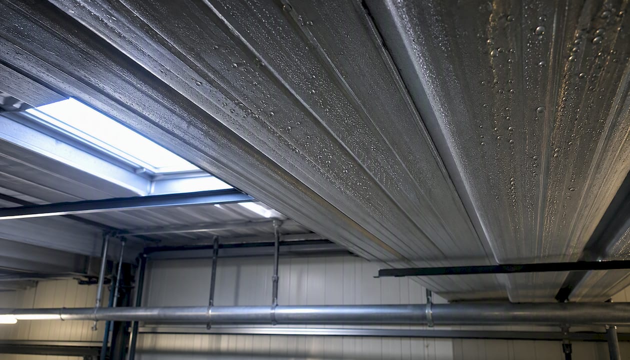
Thermal bridging compounds the problem in a different way. Every rail, bracket, and fastener that penetrates the insulation layer creates a shortcut for heat, and in a built-up cladding system there are a lot of them. SCI technical guidance provides the calculation method for accounting for spacer systems, and the effect is not trivial: a wall assembly that looks like it should hit a strong U-value on paper can fall well short once bridging is properly modelled.
Physical damage during handling causes the third major failure mode. Compressed, torn, or waterlogged fibres lose loft and, with it, insulating value. Storing rolls on damp ground, walking on installed insulation before it’s covered, or leaving polythene wrapping in place too long after unrolling all degrade performance before the building is even finished.
Pro Tip: If a roof cavity has visible staining or rust streaks on the underside of the outer sheet during a retrofit inspection, assume condensation has already been happening for years and budget for a full vapour-control redesign, not just a top-up of insulation.
Fix each failure mode with a specific, checkable measure:
- Fit a sealed AVCL on the warm side of the insulation, sized to the vapour resistance target for the building’s use.
- Model thermal bridging at design stage and adjust insulation thickness or add thermal break pads at rail junctions.
- Specify support rails or clamping systems that hold insulation at full thickness without crushing it.
- Seal every penetration, from cable entries to structural fixings, as part of the airtightness strategy.
- Where high humidity is unavoidable, consider a ventilated void behind the insulation to let residual moisture escape rather than relying solely on a perfect vapour seal.
- Dew point migration is the root cause of condensation, not a random defect.
- Bridging losses are calculable and should appear in the design U-value, not be ignored.
- Compression during storage or installation permanently reduces loft.
- Sealing penetrations is as important as the insulation specification itself.
Installing fiberglass in purlin and girt systems step by step
Sequence matters as much as product choice. Roof insulation should go in before the external sheeting closes the building up, giving installers dry conditions to work in and a chance to inspect the liner beneath. Wall insulation follows a similar logic between girts, with facing orientation checked on every single roll, since a facing installed the wrong way round defeats the entire vapour strategy.
- Confirm the liner panel or breather membrane is fitted and undamaged before insulation goes in.
- Roll fiberglass across purlins (roof) or between girts (wall), keeping the facing consistently towards the warm, occupied side of the building.
- Butt joints tightly so fibres knit together, following MCRMA’s recommendation to avoid gaps at seams and corners.
- Fit support rails, stick pins, or non-return washers to hold the insulation at full recovered thickness without sagging.
- Seal edges, penetrations, and junctions with an AVCL or purpose-made tape before the outer sheet or panel closes the assembly.
- Fit flashings and closures promptly to protect the completed section from weather exposure.
Fixing method affects long-term performance more than most site teams appreciate. Support rails spread the load evenly and reduce localised compression; stick pins and washers work well on wall assemblies where the insulation sits against a solid backing. Clamping rails across the roof pitch stop rolls from sagging under their own weight over years of service, which matters because sagged insulation leaves cold gaps at the top of the cavity exactly where warm air rises to meet it.
On-site discipline separates a compliant installation from a compromised one. Remove polythene compression wrapping only as each roll is placed, not in advance, so material isn’t exposed to weather or foot traffic before it’s covered. Avoid walking directly on installed insulation, since even light compression from boots reduces loft in that spot permanently. Install only as much as the crew can cover with sheeting or liner before the next likely rain, and protect completed sections until flashings and closures are fitted.
- Sequence: liner check, insulation placement, fixing, sealing, then external sheeting.
- Facing orientation must be checked roll by roll, not assumed from the first one.
- Support and clamping rails prevent sag over the building’s service life.
- Weather protection during installation is as critical as the finished detail.
Pro Tip: Brief the whole crew on facing orientation before the first roll goes up. A wall section installed with the vapour retarder facing outward is one of the most common and most expensive mistakes to unpick once cladding is fixed.
Do you need a vapour barrier, and how does ventilation help?
An air and vapour control layer stops warm, moist internal air reaching the cold outer skin, and it only works when it sits on the warm side of the insulation. LABCW guidance on fully supported single-skin metal roofs recommends an AVCL with a vapour resistance typically in the range of 5,000 to 7,000 MN·s/g for effective condensation control. Get the location wrong, placing an AVCL on the cold side instead, and it traps moisture inside the insulation rather than keeping it out.
Two ventilation strategies dominate metal roof design. A ventilated warm roof allows a continuous airflow above or below the insulation to carry moisture vapour away before it can condense, which suits buildings with higher internal humidity or where an AVCL might get damaged during the building’s working life. A warm non-ventilated roof relies entirely on an intact, correctly sealed AVCL doing its job without any secondary drying route, so it demands more careful detailing at every junction and penetration.
Running a proper condensation risk analysis before specification isn’t optional if you want the assembly to last:
- Identify internal humidity sources: occupancy density, wash-down processes, livestock, or manufacturing moisture.
- Calculate the expected dew point location within the assembly under typical winter conditions.
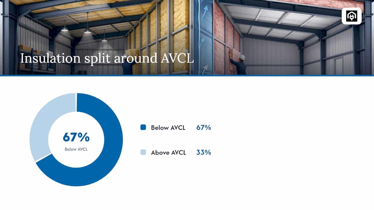
- Set the insulation ratio above and below the AVCL, commonly following a 2:1 rule where roughly twice as much insulation sits below (warm side of) the AVCL as above it, adjusted for unusual humidity loads.
- Detail every penetration, fastener, and junction for sealing, since a single gap can undermine an otherwise well-designed vapour strategy.
Pro Tip: For buildings likely to change use later, such as a warehouse that might convert to a workshop with wet processes, design the vapour strategy for the higher humidity scenario now. Retrofitting an AVCL into a finished built-up roof is far more disruptive than specifying it correctly the first time.
An AVCL with a high vapour resistance, correctly positioned and continuously sealed, is the figure most UK guidance converges on for standard single-skin metal roof applications.
Getting the thickness right: R-values, U-values, and Approved Document L
Glass mineral wool’s thermal conductivity of 0.035–0.045 W/mK translates into roughly R-1 (in imperial terms) per inch of thickness at the lower end of that range, though the exact figure depends on density and the specific product tested. That’s a useful rule of thumb for a quick estimate, but it is not a substitute for a proper U-value calculation once rails, brackets, and liner systems enter the picture.
SCI technical guidance gives worked examples for built-up cladding that illustrate the gap between nominal and effective performance: typical wall build-ups need a moderate thickness of mineral wool to meet common U-value targets, while roofs often need a thicker layer, depending on the spacer system and cladding profile used. Treat these as a starting point for early design conversations, not a final specification, because the exact figure always depends on the specific rail geometry, insulation density, and target U-value for that project.
Approved Document L, split into Part L2A for new commercial buildings and Part L2B for existing ones, sets the U-value targets designers must hit and explicitly requires calculations that account for thermal bridging rather than nominal insulation performance alone. Regulatory standards in this space have tightened over recent years, and the direction of travel is towards higher performance expectations for new builds, not lower ones. That makes a design-stage U-value calculation specific to the actual cladding system, not a generic table lookup, essential before ordering material.
- Use 0.035–0.045 W/mK as your working thermal conductivity range for glass mineral wool.
- Treat published thickness guidance as illustrative; always confirm with a project-specific U-value calculation.
- Part L2A applies to new buildings, Part L2B to existing ones undergoing work.
- Bridging from spacer systems can be the difference between passing and failing a U-value target.
Pro Tip: Ask your insulation supplier for the whole-assembly U-value, not just the insulation’s own conductivity figure. Reputable manufacturers can provide this calculated to the specific rail and bracket system you’re using.
When mineral wool, spray foam, or PIR beats fiberglass
Fiberglass earns its place in most standard-humidity metal buildings, but three alternative categories solve problems fiberglass genuinely cannot.
Mineral wool (rock wool) shares fiberglass’s non-combustible profile and A1 fire rating but typically offers slightly better acoustic performance and higher density options, making it the frequent choice for fire-rated built-up systems where compliance margins are tight. Closed-cell spray foam delivers a notably better thermal conductivity, around 0.027 W/mK according to product data cited in regulatory guidance, and its expanding application seals gaps that blanket insulation simply cannot reach. That air-sealing quality suits thin assemblies and retrofits where thermal bridging must be minimised, but spray foam is combustible and needs fire-protection measures under Part B when used in occupied commercial buildings. PIR and other rigid insulation boards suit high-performance retrofits or warm-deck roof applications where cavity depth is limited and a higher R-value per millimetre justifies the extra material cost.
Hybrid solutions often outperform any single material used alone. Mineral wool combined with a carefully detailed vapour control layer, or spray foam applied specifically at junctions and penetrations while the main field uses fiberglass or mineral wool, can deliver both thermal and acoustic performance without paying for spray foam across an entire roof.
- Mineral wool: best for fire-rated built-up systems needing acoustic performance alongside thermal.
- Closed-cell spray foam: best for thin assemblies and air-sealing where thermal bridging is a major concern.
- PIR/rigid boards: best for high-performance retrofits or warm-deck roofs with limited cavity depth.
| Material | Best for | Thermal conductivity | Moisture resistance | Fire performance | Installation | Typical cost |
|---|---|---|---|---|---|---|
| Fiberglass (glass mineral wool) | Standard built-up roofs and walls | 0.035–0.045 W/mK | Low; needs AVCL | Euroclass A1 | Fast, low skill | Lower |
| Mineral/rock wool | Fire-rated or acoustic-sensitive builds | Similar to fiberglass | Low; needs AVCL | Euroclass A1 | Fast, low skill | Moderate |
| Closed-cell spray foam | Thin assemblies, air-sealing, retrofits | Around 0.027 W/mK | High; self-sealing | Combustible, needs protection | Specialist application | Higher |
| PIR/rigid boards | High-performance retrofits, warm decks | Better than fiberglass per mm | Good | Combustible, varies by product | Moderate skill | Higher |
Budgeting for materials and labour on a metal building project
Material costs for vinyl-faced fiberglass rolls sit at the lower end of the insulation market, which is a large part of why the product remains the default choice for straightforward new-build projects. Closed-cell spray foam and PIR boards both cost meaningfully more per unit of thermal performance, a premium that buys better air-sealing or a thinner overall assembly rather than a like-for-like swap.
Labour cost depends more on access than on material choice. A high-pitch roof, extensive penetrations for rooflights and services, or a retrofit into an occupied building all add time and complexity that a straightforward new-build wall installation does not carry. Retrofit work in particular tends to cost more per square metre than new-build, because existing liners, services, and access constraints slow every stage down.
Budget beyond the raw insulation cost:
- AVCL material and specialist sealing tape, which are easy to underspecify on a tight quote.
- Thermal break pads at rail junctions if bridging modelling shows they’re needed.
- Airtightness testing or acceptance checks on moisture-sensitive or high-specification projects.
- Specialist labour for a condensation risk analysis where the building’s use involves elevated humidity.
Retrofitting fiberglass without creating a condensation problem
Retrofitting insulation into an existing metal building carries more risk than specifying it for a new one, mostly because the existing structure’s moisture behaviour is often unknown until problems appear. Do commission a condensation risk analysis before ordering material; don’t assume an exposed liner and added insulation will simply dry out on their own, because in many cases they won’t, and trapped moisture will quietly corrode the structure behind a newly finished wall.
Do protect insulation during installation and avoid compressing it against existing fixings; don’t leave compression wrapping on longer than necessary or leave gaps around obstructions that weren’t there in the original design. Do check existing ventilation provision, any humid internal processes already in use, and the likelihood of a future change of use; don’t ignore thermal bridging around retrofitted rails and brackets just because the original structure wasn’t designed with bridging calculations in mind.
Pro Tip: Before quoting a retrofit, ask the client directly whether the building’s use has changed, or is likely to change, in the next five years. A dry storage unit converting to food processing changes the entire vapour strategy, and it’s far cheaper to plan for that now than to redo the insulation later. Homeenergymodel’s guidance on practical retrofit examples covers similar sequencing principles for other building types.
- Commission a condensation risk analysis before ordering material, not after installation begins.
- Protect insulation from compression and moisture throughout the retrofit programme.
- Check current and likely future humidity conditions before finalising the vapour strategy.
- Model thermal bridging around any newly introduced rails or brackets.
What to check before you specify or hire
A clear specification checklist prevents the most common disputes between owners, contractors, and suppliers. Confirm facing type (vinyl, foil, or unfaced), density, declared thermal conductivity, Euroclass reaction-to-fire rating, and the product’s recovery characteristics after compression, then match these against the manufacturer’s own installation guidance rather than a generic industry assumption.
- Request the manufacturer’s data sheet showing declared thermal conductivity and Euroclass rating.
- Ask for evidence of experience with built-up metal cladding specifically, not general insulation work.
- Ask whether a condensation risk analysis has been carried out or is included in the quote.
- Request details of the proposed fixing method: support rails, stick pins, or clamping systems.
- Confirm what warranty covers the installation, not just the material.
Before signing off any contract, ask for a site-specific build-up drawing showing every layer from structure to outer sheet, a record of the U-value calculation method used, and, on moisture-sensitive projects, a plan for acceptance testing of airtightness. Homeenergymodel’s energy loss assessment guidance offers a useful parallel framework for the kind of diagnostic thinking that should underpin any condensation risk analysis.
- Facing type, density, and fire rating should all appear on the specification, not just the quote.
- Contractor experience with built-up cladding matters more than general insulation experience.
- A site-specific build-up drawing and U-value record protect both parties if problems emerge later.
What MCRMA, Approved Document L, and industry guidance actually require
MCRMA’s guidance on mineral wool in built-up cladding systems is the closest thing the UK metal building sector has to a shared installation standard. It covers storage, handling, compression recovery, and the need to account for thermal bridging in the final U-value figure, not just the insulation’s nominal performance. Any contractor working on built-up metal roofs or walls should be familiar with it.
Approved Document L governs the U-value targets themselves, with Part L2A covering new commercial buildings and Part L2B covering existing ones undergoing work. Part B, separately, governs fire safety and becomes especially relevant when combustible insulants such as spray foam or certain rigid boards are being considered instead of non-combustible mineral wool. None of these documents replace the need for a design-stage U-value calculation specific to the actual cladding system being used; generic thickness tables are a starting point for conversation, never a final answer.
The consistent thread across MCRMA, Approved Document L, and structural steel guidance is that a built-up metal assembly’s real performance depends on the whole system, insulation, spacers, AVCL, and fixings together, not on any single product’s data sheet in isolation.
- MCRMA covers installation best practice and thermal bridging awareness for mineral wool systems.
- Approved Document L (Part L2A/L2B) sets U-value targets designers must meet.
- Part B governs fire safety implications when combustible insulants are used.
- A design-stage U-value calculation, specific to the cladding system, is the only reliable compliance route.
Homeenergymodel’s take on fitting insulation to the building’s real use
Fiberglass is the right call for a large share of metal buildings, and specifying anything more expensive as a default is usually money spent solving a problem that doesn’t exist. Where it goes wrong is almost never the material itself; it’s a missing or badly positioned AVCL, or a design team that priced the insulation without pricing the condensation risk analysis that should sit alongside it.
The practical rule worth remembering: treat moisture strategy and material choice as one decision, not two. A contractor who can install fiberglass beautifully but can’t explain where the vapour control layer sits, or why, is a bigger risk to a project than the insulation product they’ve chosen. Ask that question before the material question, every time.
Frequently asked questions
Can you use fiberglass insulation in a metal building?
Yes, in most standard-humidity commercial and agricultural buildings, provided the design includes a correctly positioned AVCL and a design-stage U-value calculation that accounts for thermal bridging.
Does fiberglass insulation cause condensation in metal buildings?
Fiberglass itself doesn’t cause condensation, but its lack of vapour resistance means it won’t stop condensation forming if warm, moist air reaches the cold underside of the outer metal sheet without an AVCL in place.
What thickness of fiberglass insulation do metal buildings need?
It depends on the U-value target and the specific rail and bracket system, but illustrative ranges from SCI guidance suggest roughly 110–130 mm for walls and 160–200 mm for roofs; always confirm with a project-specific calculation.
Is spray foam better than fiberglass for metal buildings?
Spray foam offers higher thermal performance per millimetre and better air-sealing, making it suited to thin assemblies, but it’s combustible and needs fire-protection measures under Part B, whereas fiberglass achieves a non-combustible Euroclass A1 rating.
Do I need a separate vapour barrier with vinyl-faced fiberglass rolls?
Often not, since the vinyl facing frequently functions as an integral vapour retarder for standard-humidity buildings, though very humid interiors or extreme heating conditions still warrant a dedicated vapour barrier.
How do I check if my metal building’s insulation meets Approved Document L?
Request a design-stage U-value calculation specific to the cladding system in use, covering Part L2A for new buildings or Part L2B for existing ones, rather than relying on generic thickness tables.
Sources
- MCRMA guidance GD28 – Mineral wool insulation installation: Best practice guide
- LABCW guidance — Fully supported single skin metal roofs (AVCL recommendations)
- Duratite — Spray foam building regulations guidance
- Fiberglass insulation resources & installation guide — Factory Steel Overstock